
Page 3 - Trenching & Shoring E-Catalogue
P. 3
Introduction / 2
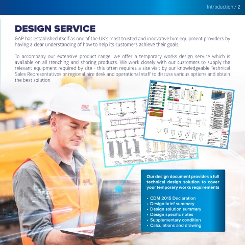
DESIGN SERVICE
GAP has established itself as one of the UK’s most trusted and innovative hire equipment providers by
having a clear understanding of how to help its customers achieve their goals.
To accompany our extensive product range, we offer a temporary works design service which is
available on all trenching and shoring products. We work closely with our customers to supply the
relevant equipment required by site - this often requires a site visit by our knowledgeable Technical
Sales Representatives or regional hire desk and operational staff to discuss various options and obtain
the best solution.
Pre-excavation Checks:
Check 1: Adjacent Highway/Plant Surcharge do not
exceed 10kN/m 2 (Up to 30T construction plant)
OK:
Table 1: Soil Conditions
Excavation Plan dimension is within the range of
OK: Suitable Ground Conditions 10kN/m² Surcharge
Check 2: Min. 2067mm and Max. 3967mm (External)
Prohibited Ground Conditions (30Te Plant)
Made Ground
No natural or battered ground within the (Compacted) Made Ground General Notes:
excavation (Loose) 0.0m
Check 3: 'excavation depth + 1m' from the edge of the
OK: Rock (Mudstone/
Sandstone/Limestone/ 1. All dimensions are in
(e.g. PEAT)
Check 4: Siltstone/Chalk) Organic Materials otherwise.
millimeters unless noted
(including accidental overdig) Loose/Medium/Dense
Excavation depth does not exceed 3.9m
OK: Granular Materials 2. This drawing has been
including Boulders, prepared with reasonable
Cobbles, Gravels & Very Loose Gravels / Max Excavation Depth 3.9m skill and care from the
Sands. Sands/Silt. information supplied to us
Check 5: * Please Refer to Table 1 for Soil Conditions
Soft to Firm/Firm/Firm to
OK: Stiff/Stiff/Stiff to very Stiff 40.0kN/m² Excavation by the client, the client to
ensure all the assumed
Clay Soft / Very Soft Clay Depth loading, dimensions and
Pressure Envelope -3.9m dig level, installation and
OK: extraction are correct.
Check 6: No Groundwater present
OK: Soil Profile
NOT OK: Gronundwater Level 3. Gap Group Ltd. accept no
TYPICAL BOX SECTION responsibility or liability for
amendments or alterations
made to this drawing
No building/structures with the zone of influence
Check 7: (excavation depth + 1m) is present from the edge
of the excavation. 2067 - 2162
OK: 2158 - 2358 RESIDUAL RISKS without the consent of Gap
Group Ltd.
2358 - 2558
Check 8: 2358 - 2758 Ground 4. This drawing to be read in
No sensitive services present within the
excavating planed area 2358 - 3158 Conditions If the ground condition and the groundwater conjunction with all other
relevant temporary works
OK: 3500 2358 - 3967 level is different than shown on this drawing, it drawings and
is the responsibility of the customer to inform
3500 3000 Gap Group Ltd. for review. documentation.
Groundwater
equipments must be
3500 Conditions If Groundwater is encountered during the 5. All temporary work
Pre Excavation Check Complete.
Standard Solution OK to Use 3500 excavation, a site specific design is required. It installed by a competent
is the responsibility of the customer to provide a
and experienced
3500 Surcharges safe working environment at all times. temporary work contractor
This design allows for a 30T construction plant
If any of the above criteria is not met, Existing load and the local ground reduction. familiar with this type of
temporary works.
Structures This design is based on the assumptions that 6. All temporary works to be
then a bespoke design is required.
there are no existing structures with the zone of
properly supervised, with
influence of the excavation. If this is not the case
personal provided with safe
the customer should contact Gap Group Ltd.
working platforms (as
Ground required).
IF SITE CONDITIONS CHANGE DURING INSTALLATION, THE
WORK SHOULD BE STOPPED AND TEMPORARY WORKS
(Not In Scale) Movement There will be some ground movements (lateral
TYPICAL CONFIGURATIONS FOR MIN/MAX PLAN DIMS FOR 3.5m STANDARD MANHOLE BOXES
COORDINATOR SHOULD BE INFORMED.
and settlment) behind the box due to disturbing
7. All proprietary equipments
IF IN DOUBT CONTACT GAP GROUP ENGINEERING
the soil, Gap Group Ltd. will accept no
to be installed in
DEPARTMENT. responsibility for the consequences of the ground accordance with the
movement on any structures around the
excavation. manufacturer's
recommendations.
Buildability 8. According to the CDM
Please refer to the installation sequence prior to
installing the equipment. 2015, Gap Group Hire Ltd
and/or the Client adopt the
Edge
Protection role of Designer as part of
this project and have the
Suitable edge protection to be provided around
the perimeter of the excavation. Access and fall
responsibility to comply
with our duties under
arrest systems should also be considered and
Stage 1 are the responsibility of the customer.
Overdig regulation 9, CDM 2015.
Stage 2
Our responsibility include
This design does not allow for overdig beyond
Stage 3 the formation level shown. It is the responsibility taking account of
Pre-construction
not to exceed this depth.
of the customer to take care when excavating
Stage 4 Method of information (PCI) to
Installation Refer to the installation sequence on the drawing. eliminate, reduce or control
(Not In Scale) Stage 5 Customer to ensure boxes are pushed to final to foreseeable risks in their
TYPICAL ASSEMBLY SEQUENCE FOR 3.5m STANDARD MANHOLE BOXES
Monitoring level prior to excavation works commencing. designs to reduce or
It is recommended that the customer monitors the
control risks not eliminated. AL 10.02.21
excavation and the surrounding area for signs of
FILE NAME: C:\Users\ahmad.laly\Desktop\Gap Projects\Standard Solution\7. Standard Manhole Box (3.5m)\3.5m Standard Manhole Box.dwg PLOT DATE: 18/02/2021 PLOT SCALE: 1:1 Stage 1 Stage 2 Stage 3 Stage 4 Site Address: xxx Contract Details REV. REVISIONS DETAILS 40 Carrick St, Carrick House, DR. DATE
movement or distress throughout the works.
C01 FIRST ISSUE
Client:
xxx
Contract Number: xxx
Glasgow, G2 8DA, United Kingdom
Tel: +44 (0) 141 225 4600
Stage 5
www.gap-group.co.uk info@gap-group.co.uk
Checked and Signed By:
Title:
3.5m STANDARD MANHOLE BOX
(Not In Scale) Stage 6 I certify to the best of my knowledge the actual site and ground Contract: 3.9m MAXIMUM DEPTH
Works Design.
TYPICAL INSTALLATION SEQUENCE FOR TRENCH BOXES- DIG AND PUSH METHOD OF INSTALLATION
Stage 7 DIG AND PUSH METHOD OF
conditions do not conflict with the parameters of this Temporary
INSTALLATION
Signed: Client:
Certified By: (Print name)
(signature or print name)
Date: STANDARD SOLUTION
Company: xxx DRG. STATUS:
Gap Group Hire Ltd. Paper Size: Scale: Designed By:
As Checked By: Drawn By:
A1 Shown A. Laly
Internal Reference Number: O. Chaudhry A. Laly
XXXXX Date:
*Note: Drawing status "Construction Issue" only valid when signed by a certified person.
Drawing Number: 11.02.21 Issue:
STD-GAP-XX-XX-DR-Y-0007 C01
Our design document provides a full
technical design solution to cover
your temporary works requirements
• CDM 2015 Declaration
• Design brief summary
• Design solution summary
• Design specific notes
• Supplementary condition
• Calculations and drawing